
CENTRIFUGAL PUMP SYSTEMS TIPS
|
This is a list of ideas or DOS AND DON'TS for pump systems. You may not of thought of some of these and they will help you design and trouble-shoot pump systems and select the proper pump. Also there is information here that is hard to find elsewhere. You can think of this list as GUIDELINES for the pump system designer. You can also download these tips |

1. Flow and pressure relationship of a pump
When the flow increases, the discharge pressure of the pump decreases, and when the flow decreases the discharge pressure increases (ref. tutorial2.htm).
2. Do not let a pump run at zero flow
Do not let a centrifugal pump operate for long periods of time at zero flow. In residential systems, the pressure switch shuts the pump down when the pressure is high which means there is low or no flow.
Make sure your pump has a pressure gauge on the discharge side close to the outlet of the pump this will help you diagnose pump system problems. It is also useful to have a pressure gauge on the suction side, the difference in pressure is proportional to the total head. The pressure gauge reading will have to be corrected for elevation since the reference plane for total head calculation is the suction flange of the pump.
These web apps will help you calculate total head from pressure
4. Do not let a pump run dry, use a check valve
Most centrifugal pumps cannot run dry, ensure that the pump is always full of liquid. In residential systems, to ensure that the pump stays full of the liquid use a check valve
(also called a ![]() foot valve) at the water source end of the suction line. Certain types of centrifugal pumps do not require a check valve as they can generate suction at the pump inlet to lift the fluid into the pump. These pumps are called jet pumps and are fabricated by many manufacturers Goulds being one of them.
foot valve) at the water source end of the suction line. Certain types of centrifugal pumps do not require a check valve as they can generate suction at the pump inlet to lift the fluid into the pump. These pumps are called jet pumps and are fabricated by many manufacturers Goulds being one of them.
Make use of check valves to isolate pumps installed in parallel.
Gate valves at the pump suction and discharge should be used as these offer no resistance to flow and can provide a tight shut-off. Butterfly valves are often used but they do provide some resistance and their presence in the flow stream can potentially be a source of hang-ups which would be critical at the suction. They do close faster than gate valves but are not as leak proof.
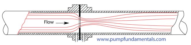
Always use an eccentric reducer at the pump suction when a pipe size transition is required. Put the flat on top when the fluid is coming from below or straight (see next Figure) and the flat on the bottom when the fluid is coming from the top. This will avoid an air pocket at the pump suction and allow air to be evacuated.

7. Use a multi-stage turbine pump for deep wells
For deep wells (200-300 feet) a submersible multi-stage pump is required. They come in different sizes (4" and 6") and fit inside your bore hole pipe. Pumps with different ratings are available.
If you need to control the flow, use a valve on the discharge side of the pump, never use a valve on the suction side for this purpose.
This is an excellent treatment of ![]() the types of control systems for a centrifugal pump by Walter Driedger.
the types of control systems for a centrifugal pump by Walter Driedger.
And also this article by the same author ![]() on how to control positive displacement pumps.
on how to control positive displacement pumps.
For new systems that do not have a flow meter, install flanges that are designed for an orifice plate in a straight part of the pipe (see next Figure) and do not install the orifice plate. In the future, whoever trouble-shoots the pump will have a way to measure flow without the owner having to incur major downtime or expense. Note: orifice plates are not suitable for slurries.
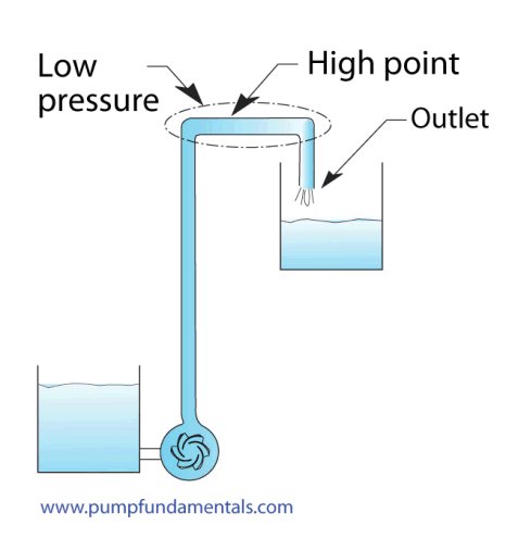
10. Avoid pockets and high points
Avoid pockets or high point where air can accumulate in the discharge piping. An ideal pipe run is one where the piping gradually slopes up from the pump to the outlet. This will ensure that any air in the discharge side of the pump can be evacuated to the outlet.
Be aware of potential water hammer problems. This is particularly serious for large piping systems such as are installed in municipal water supply distribution systems. These systems are characterized by long gradually upward sloping and then downward sloping pipes. Solutions to this can involve special pressure/vacuum reducing valves at the high and low points or additional tanks which provide a buffer for pressure surges (see ventomat).
see also the pump glossary
For pumps 500 gals/min or larger use semi-automatic manual valves at the discharge that are controlled to open gradually when starting the pump. This will avoid water hammer during the initial start and damage to the piping system.
The right pipe size is a compromise between cost (bigger pipes are more expensive) and excessive friction loss (small pipes cause high friction loss and will affect the pump performance). Generally speaking, the discharge pipe size can be the same size as the pump discharge connection, you can see if this is reasonable by calculating the friction loss of the whole system. For the suction side, you can also use the same size pipe as the pump suction connection, often one size bigger is used (ref. tutorial3.htm). A typical velocity range used for sizing pipes on the discharge side of the pump is 9-12 ft/s and for the suction side 3-6 ft/s.
See this calculator for velocity and flow>
A small pipe will initially cost less but the friction loss will be higher and the pump energy cost will be greater. If you know the cost of energy and the purchase and installation cost of the pipe you can select the pipe diameter based on a comparison of the pipe cost vs power consumption.
14. Pressure at high point of system
Calculate the level of pressure of the high point in your system. The pressure may be low enough for the fluid to vaporize and create a vapor pocket which will be detrimental to the performance of the system. The pressure at this point can be increased by installing a valve at some point past the high point and by closing this valve you can adjust the pressure at the high point. Of course, you will need to take that into account in the total head calculations of the pump.
See this video showing this phenomena in action.
15. Pump pressure rating and series operation
For series pump installations make sure that the pressure rating of the pumps is adequate. This is particularly critical in the case where the system could become plugged due to an obstruction. All the pumps will reach their shut-of head and the pressure produced will be cumulative. The same applies for the pressure rating of the pipes and flanges.

16. Inadequate pump suction submersion
There is a minimum height to be respected between the free surface of the pump suction tank and the pump suction. If this height is not maintained a vortex will form at the surface and cause air to be entrained in the pump reducing the pump capacity.
see the pump system glossary also see this experiment on video that shows vortex formation.
Select your pump based on total head (not discharge pressure) and flow rate. The flow rate will depend on your maximum requirement. Total head is the amount of energy that the pump needs to deliver to account for the elevation difference and friction loss in your system (ref. tutorial3.htm).
Pump selection starts with acquiring detail knowledge of the system. If you are just replacing an existing pump then of course there is no problem. If you are replacing an existing pump with problems or looking for a pump for a new application then you will need to know exactly how the systems is intended to work. You should have the P&ID diagram and understand the reasons for all the devices included in your system. You should make your own sketch of the system that includes all the information on the P&ID plus elevations (max., min., in, out, equipment), path of highest total head, fluid properties, max. and min. flow rates and anything pertinent to total head calculations.
The next figure is a typical example:

Typical example of flow schematic used for total head calculations.
The control method is important (on-off, control valve, re-circulating, variable speed) as it may affect your selection. Besides the system sketch, here is a pump data sheet![]() that you can use to record some of the data.
that you can use to record some of the data.
Depending on the industry or plant that you work in, you will be forced to either select a certain type of pump or manufacturer or both. Manufacturers are normally a very good source of information for final pump selection and you should always consult with them, do your own selection first and confirm it with the manufacturer. They can help you select the right type, model, and speed if you have all the operating conditions and if not they will rarely be able to help you. This form will help you gather all the information pertinent to operation and selection of your pump![]() .
.
Aside from the normal end suction pump, vertical turbine and submersible pumps, there is a wide variety of specialized pumps![]() that you should consider for your application if you have unusual conditions.
that you should consider for your application if you have unusual conditions.
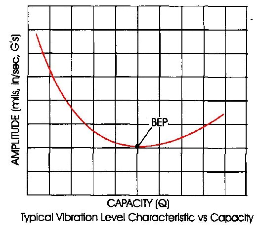
In the selection process, you will be trying to match your flow rate with the B.E.P. of the pump. It is not always possible to match the flow rate with the B.E.P. (best efficiency point), if this is not possible, try to remain in the range of 80% to 110% of the B.E.P..

Desirable selection area for impeller size for centrifugal pumps.
Operating outside this range will lead to excessive vibration, recirculation and cavitation, see the next two figures. The first one from the Pump Handbook from McGraw-Hill which shows how the axial force increases with the distance in terms of percent flow from the B.E.P. and the second from Goulds essentially shows the same information but in terms of vibration.

Radial force vs. % flow of BEP
When you order your pump make sure that the motor is installed with spacer blocks so that the next largest motor frame can be installed.
See also item 30 on selecting high speed centrifugal pumps.
18. Air in pump reduces capacity
When air enters a pump it sometimes gets trapped in the volute, this reduces the capacity, creates vibration and noise. To remedy, shut the pump down and open the vent valve to remove the air. If the pump is excessively noisy do not automatically assume that the problem is cavitation, air in the pump creates vibration and noise. Cavitation produces a distinct noise similar to gravel in a cement mixer. If you have never heard the sound of cavitation here's a recording![]() of it in WAV format, courtesy of my friend Normand Chabot, water hammer specialist here in Montreal.
of it in WAV format, courtesy of my friend Normand Chabot, water hammer specialist here in Montreal.
see also the pump glossary
Also see articles on entrained air on this web page: pumpworld.htm
19. Effect of viscosity on pump performance
Viscosity is the main criteria which determines whether the application requires a centrifugal pump or a positive displacement pump. Centrifugal pumps can pump viscous fluids however the performance is adversely affected. If your fluid is over 400 cSt (centiStokes) in viscosity consider using a positive displacement pump.
see also the pump glossary
Also see articles on viscosity on this web page: pumpworld.htm
20. Avoid running pump in reverse direction
Avoid running a pump in reverse direction, pump shafts have been broken this way especially if the pump is started while running backwards. The simplest solution is to install a check valve on the discharge line.
Most centrifugal pumps should not be used at a flow rate less than 50% of the B.E.P. (best efficiency point) flow rate without a recirculation line. (What is the B.E.P.?) If your system requires a flow rate of 50% or less then use a recirculation line to increase the flow through the pump keeping the flow low in the system, or install a variable speed drive.
see also the pump glossary BEP
The factors which determine minimum allowable rate of flow include the following:
* Temperature rise of the liquid -- This is usually established as 15°F and results in a very low limit. However, if a pump operates at shut off, it could overheat badly.
* Radial hydraulic thrust on impellers -- This is most serious with single volute pumps and, even at flow rates as high as 50% of BEP could cause reduced bearing life, excessive shaft deflection, seal failures, impeller rubbing and shaft breakage.
* Flow re-circulation in the pump impeller -- This can also occur below 50% of BEP causing noise, vibration, cavitation and mechanical damage.
* Total head characteristic curve - Some pump curves droop toward shut off, and some VTP curves show a dip in the curve. Operation in such regions should be avoided.
There is no standard which establishes precise limits for minimum flow in pumps, but "ANSI/HI 9.6.3-1997 Centrifugal and Vertical Pumps - Allowable Operating Region" discusses all of the factors involved and provides recommendations for the "Preferred Operating Region".
22. Three important points on the pump characteristic curve
The performance or characteristic curve of the pump provides information on the relationship between total head and flow rate. There are three important points on this curve.

1. The shut-off head, this is the maximum head that the pump can achieve and occurs at zero flow. The pump will be noisy and vibrate excessively at this point. The pump will consume the least amount of power at this point. See also the pump glossary.
2. The best efficiency point B.E.P. this is the point at which the pump is the most efficient and operates with the least vibration and noise. This is often the point for which pump’s are rated and which is indicated on the nameplate. The pump will consume the power corresponding to its B.E.P. rating at this point.
3. The maximum flow point, the pump may not operate past this point. The pump will be noisy and vibrate excessively at this point. The pump will consume the maximum amount of power at this point.
Sometimes the characteristic curve will include a power consumption curve. This curve is only valid for water, if the fluid has a different density than water you cannot use this curve. However you can use the total head vs. flow rate curve since this is independent of density.

Typical centrifugal pump characteristic curve.
If your fluid has a different viscosity than water you cannot use the characteristic curve without correction. Any fluid with a viscosity higher than 10 cSt will require a correction. Water at 60F has a viscosity of 1 cSt.
23. Normal, flat and drooping characteristic curves
There are three different characteristic curve profiles for radial flow pumps.![]() Figure 4 shows the various vane profiles that exist and the relationship between them. This tip is related to the radial vane profile which is the profile of the typical centrifugal pump.
Figure 4 shows the various vane profiles that exist and the relationship between them. This tip is related to the radial vane profile which is the profile of the typical centrifugal pump.
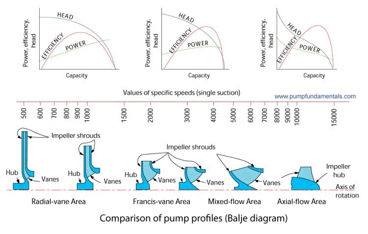
Pump vane profiles vs. specific speed.
There are three different curve profiles shown in the next figure:
1. Normal, head decreases rapidly as flow increases
2. Flat, head decreases very slowly as flow increases
3. Drooping, similar to the normal profile except at the low flow end where the head rises then drops as it gets to the shut-off head point.
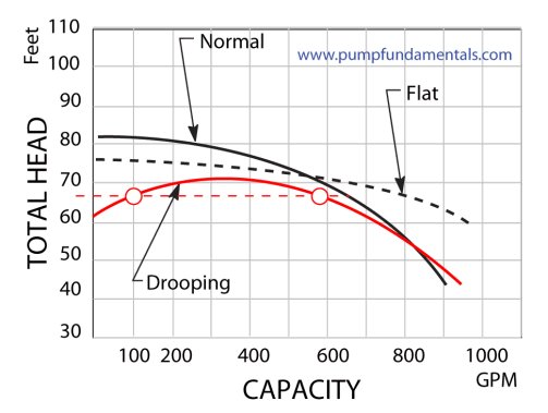
Different types of radial pump characteristic curve profiles.
The drooping curve shape is to be avoided because it is possible for the pump to hunt between two operating points which both satisfy the head requirement of the system. This is known to happen when two pumps are in parallel, when the second pump is started it may fail to get to the operating point or hunt between two points that are at equal head. Thankfully not to many pumps have this characteristic, here are a few:

Drooping curve (Goulds).

Drooping curve (Sundyne).
A flat curve is sometimes desirable since a change in flow only causes a small change in head, for example as in a sprinkler system. As more sprinklers are turned on the head will tend to decrease but because the curve is flat the head will decrease only a small amount which means that the pressure at the sprinkler will drop only a small amount, thereby keeping the water velocity high at the sprinkler outlet. The National Fire Prevention Association (N.F.P.A.) code stipulates that the characterictic curve must be flat within a certain percentage.
The normal curve can be more or less steep. A steep curve can be desirable from a control point of view since a small change in flow will result in a large pressure drop. The steepness of the curve depends on the number of vanes and the specific speed.

Many people are way to CONSERVATIVE about suction piping design. The usual advice you get is make the piping as straight, as big and short as possible.
I have seen a suction line 300 ft long, now that's not short.
I believe the important considerations are:
- by all means make the pipe as short and straight as possible, particularly if the fluid has suspended solids which may cause plugging or hangups.
- make sure there is sufficient pressure at the pump suction (this means check the NPSHA against the NPSHR);
- make sure that the stream flow lines are coming in nice and straight at the pump suction.
This generally means having 5 to 10D straight pipe ahead of the pump inlet.
Avoid the use of filters at the pump inlet if at all possible. Their maintenance will often be neglected and the pump will suffer from poor performance and perhaps cavitation.
Use a 90° or 45° elbow at the pump’s inlet pipe end. This will allow almost complete drainage of the tank and is especially useful in the case of fluids that can not be readily dumped to the sewers. It also provides additional submergence reducing the risk of vortex formation.

Also be careful of elbows that are too close to the pump suction, see the pump glossary.
25. The meaning of specific speed
If you are having trouble with a pump or want to check whether the new pump to be installed is appropriate, check the specific speed and the suction specific speed of the pump. The specific speed provides a number which can help identify the type of pump (for example radial or axial flow) that is best suited for your application. The specific speed of the pump type selected (see Figure 4) should be close to the specific speed calculated for your application. The suction specific speed will tell you if the suction of the pump is likely to cause problems in your application. Web appp for specific speed.
see also the pump glossary.
26. Different types of centrifugal pumps
There are many different types of pumps available other than the standard end suction, submersible or vertical multi-stage pump. In this article, you will see a number of pumps that are specialized![]() and may suit a particular need.
and may suit a particular need.
27. Unusual aspects of pump systems
This article discusses unusual aspects of pump systems![]() : variation in pressure throughout the system and effect of fluid properties. To calculate the pressure anywhere in a system
: variation in pressure throughout the system and effect of fluid properties. To calculate the pressure anywhere in a system![]() use this applet.
use this applet.
Save time in the initial phase of the project and calculate power requirement prior to the final pump selection and compare the efficiency of the final pump selection with the industry average.
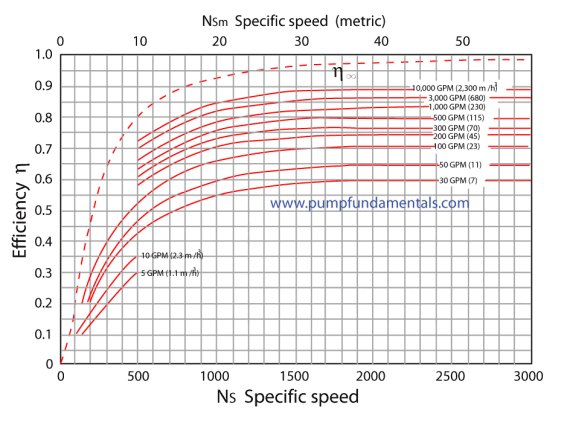
You will notice that efficiency increases with specific speed, this means that a pump with a higher speed (rpm) that meets your requirements will be smaller and more efficient and therefore cost less to operate, see item 30.
Predict the pump N.P.S.H.R. with this chart. If you have an old centrifugal pump and no data from the manufacturer this chart can help you predict the NPSH required and avoid cavitation. You will need to know the suction eye velocity which depends on the eye diameter.


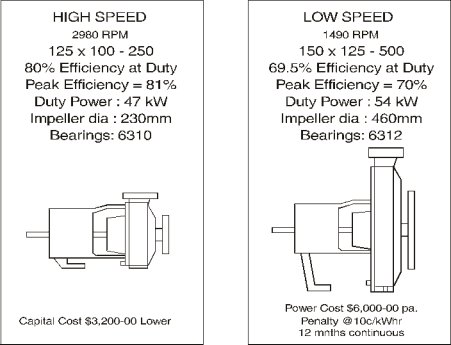
30. Consider higher speed centrifugal pumps
The standard motor induction speeds that are most often considered for pumps are 900, 1200, 1800 and 3600 rpm. The specific speed of a pump depends on its speed and the higher the specific speed the higher the efficiency (see the chart in item 28). By choosing a higher speed pump the pump will be smaller and maybe less expensive. Modern anti-friction bearings are quite capable of handling these higher speeds without compromising their useful life. Will there be increased wear within the casing? Probably not since for the same head the fluid particle speed within the casing will be the same because of the smaller impeller diameter turns at a higher rpm giving roughly similar linear velocities.
Therefore, if you want to conserve energy and reduce costs always check to see if a centrifugal pump running at a higher speed can meet your requirement. However, you should check the suction specific speed number and make sure it is below 11000 to avoid problems with cavitation.
The following is a selection of two pumps at different speeds for an application requiring 55 l/s at 70 m, by using the higher speed pump, the power savings could be very significant over time.
Also see articles on the effect of pump speed on this web page: pumpworld.htm
31. Flywheel effect, pulley diameter
Many pumps are still driven by pulleys, and large pulleys become flywheels. Flywheel pulleys have a limiting safe rotational speed. The flow can be increased by changing the pulley diameters, be careful not to exceed the safe operational speed of the pulleys.
32. 10 ways to select a happy pump
(from Robert Perez of pump calcs)

TOP
Copyright 2019, PumpFundamentals.com