CENTRIFUGAL PUMP SYSTEM TUTORIAL
What is friction in a pump system (cont.) Another cause of friction is all the fittings (elbows, tees, y's, etc) required to get the fluid from point A to B. Each one has a particular effect on the fluid streamlines. For example in the case of the elbow, the fluid particles that are closest to the tight inner radius of the elbow lift off from the pipe surface forming small vortices that consume energy. This energy loss is small for one elbow but if you have several elbows and other fittings the total can become significant. Generally speaking they rarely represent more then 30% of the total friction due to the overall pipe length. |
Figure 9
Energy and head in pump systems
Energy and head are two terms that are often used in pump systems. We use energy to describe the movement of liquids in pump systems because it is easier than any other method. There are four forms of energy in pump systems: pressure, elevation, friction and velocity.
Pressure is produced at the bottom of the reservoir because the liquid fills up the container completely and its weight produces a force that is distributed over a surface which is pressure. This type of pressure is called static pressure. Pressure energy is the energy that builds up when liquid or gas particles are moved slightly closer to each other and as a result they push outwards in their environment. A good example is a fire extinguisher, work was done to get the liquid into the container and then to pressurize it. Once the container is closed the pressure energy is available for later use.
Elevation energy is the energy that is available to a liquid when it is at a certain height. If you let it discharge it can drive something useful like a turbine producing electricity.
Friction energy is the energy that is lost to the environment due to the movement of the liquid through pipes and fittings in the system.
Velocity energy is the energy that moving objects have. When a baseball is thrown by a pitcher
he gives it velocity energy also called kinetic energy. When water comes out of a garden hose, it has velocity energy.
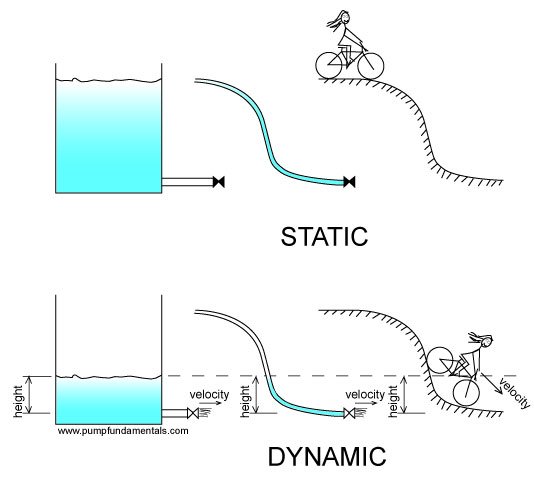
Figure 9a
In the figure above we see a tank full of water, a tube full of water and a cyclist at the top of a hill. The tank produces pressure at the bottom and so does the tube. The cyclist has elevation energy which he will be using as soon as he moves.
As we open the valve at the tank bottom the fluid leaves the tank with a certain velocity, in this case pressure energy is converted to velocity energy. The same thing happens with the tube. In the case of the cyclist, the elevation energy is gradually converted to velocity energy.
The three forms of energy: elevation, pressure and velocity interact with each other in liquids. For solid objects there is no pressure energy because they don’t extend outwards like liquids filling up all the available space and therefore they are not subject to the same kind of pressure changes.
The energy that the pump must supply is the friction energy plus the elevation energy.
PUMP ENERGY = FRICTION ENERGY + ELEVATION ENERGY

Figure 9b
You are probably thinking where is the velocity energy in all this. Well if the liquid comes out of the system at high velocity then we would have to consider it but this is not a typical situation and we can neglect this for the systems discussed in this article.
The last word on this topic, it is actually the velocity energy difference that we would need to consider. In figure 9c the velocities at point 1 and point 2 are the result of the position of the fluid particles at points 1 and 2 and the action of the pump. The difference between these two velocity energies is an energy deficiency that the pump must supply but as you can see the velocities of these two points will be quite small.
Now what about head? Head is actually a way to simplify the use of energy. To use energy we need to know the weight of the object displaced.
Elevation energy E.E. is the weight of the object W times the distance d:
EE = W x d
Friction energy FE is the force of friction F times the distance the liquid is displaced or the pipe length l:
FE = F x l
Head is defined as energy divided by weight or the amount of energy used to displace a object divided by its weight. For elevation energy, the elevation head EH is:
EH = W x d / W = d
For friction energy, the friction head FH is the friction energy divided by the weight of liquid displaced:
FH = FE/W = F x l / W (see Figure 9b)
The friction force F is in pounds and W the weight is also in pounds so that the unit of friction head is feet. This represents the amount of energy that the pump has to provide to overcome friction.

I know you are thinking this doesn’t make sense, how can feet represent energy?
If I attach a tube to the discharge side of a pump, the liquid will rise in the tube to a height that exactly balances the pressure at the pump discharge. Part of the height of liquid in the tube is due to the elevation height required (elevation head) and the other is the friction head and as you can see both are expressed in feet and this is how you can measure them.
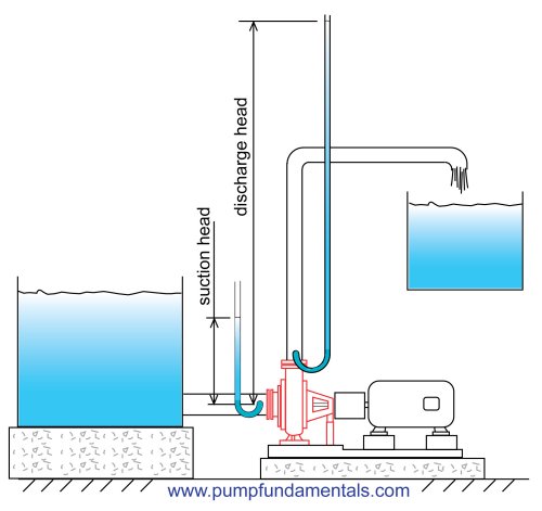
Figure 9c
Webster’s dictionary definition of head is: “a body of water kept in reserve at a height”.

It is expressed in terms of feet in the Imperial system and meters in the metric system. Because of its height and weight the fluid produces pressure at the low point. The higher the reservoir, the higher the pressure.

The amount of pressure at the bottom of a reservoir is independent of its shape, for the same liquid level, the pressure at the bottom will be the same. This is important since in complex piping systems it will always be possible to know the pressure at the bottom if we know the height. To find out how to calculate pressure from height go to the end of this article.

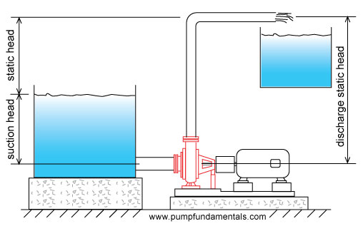
When a pump is used to displace a liquid to a higher level it is usually located at the low point or close to it. The head of the reservoir which is called static head will produce pressure on the pump that will have to be overcome once the pump is started.
To distinguish between the pressure energy produced by the discharge tank and suction tank, the head on the discharge side is called the discharge static head and on the suction side the suction static head.

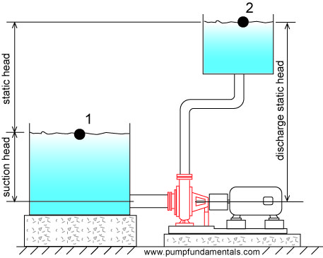
Usually the liquid is displaced from a suction tank to a discharge tank. The suction tank fluid provides pressure energy to the pump suction which helps the pump. We want to know how much pressure energy the pump itself must supply so therefore we subtract the pressure energy provided by the suction head. The static head is then the difference in height of the discharge tank fluid surface minus the suction tank fluid surface. Static head is sometimes called total static head to indicate that the pressure energy available on both sides of the pump has been considered.
Since there is a difference in height between the suction and discharge flanges or connections of a pump by convention it was agreed that the static head would be measured with respect to the suction flange elevation.
If the discharge pipe end is open to atmosphere then the static head is measured with respect to the pipe end.
Sometimes the discharge pipe end is submerged, then the static head will be the difference in elevation between the discharge tank fluid surface and the suction tank fluid surface. Since the fluid in the system is a continuous medium and all fluid particles are connected via pressure, the fluid particles that are located at the surface of the discharge tank will contribute to the pressure built up at the pump discharge. Therefore the discharge surface elevation is the height that must be considered for static head. Avoid the mistake of using the discharge pipe end as the elevation for calculating static head if the pipe end is submerged.
Note: if the discharge pipe end is submerged, then a check valve on the pump discharge is required to avoid backflow when the pump is stopped.

The static head can be changed by raising the surface of the discharge tank (assuming the pipe end is submerged) or suction tank or both. All of these changes will influence the flow rate.

To correctly determine the static head follow the liquid particles from start to finish, the start is almost always at the liquid surface of the suction tank, this is called the inlet elevation. The end will occur where you encounter an environment with a fixed pressure such as the open atmosphere, this point is the discharge elevation end or outlet elevation. The difference between the two elevations is the static head. The static head can be negative because the outlet elevation can be lower than the inlet elevation.
Flow rate depends on elevation difference or static head
For identical systems, the flow rate will vary with the static head. If the pipe end elevation is high, the flow rate will be low (see Figure 10). Compare this to a cyclist on a hill with a slight upward slope, his velocity will be moderate and correspond to the amount of energy he can supply to overcome the friction of the wheels on the road and the change in elevation.

Figure 10
See this video for the effect of static head and friction![]() .
.
If the liquid surface of the suction tank is at the same elevation as the discharge end of the pipe then the static head will be zero and the flow rate will be limited by the friction in the system. This is equivalent to a cyclist on a flat road, his velocity depends on the amount of friction between the wheels and the road and the air resistance (see Figure 11).

Figure 11
In Figure 12, the discharge pipe end is raised vertically until the flow stops, the pump cannot raise the fluid higher than this point and the discharge pressure is at its maximum. Similarly the cyclist applies maximum force to the pedals without getting anywhere.
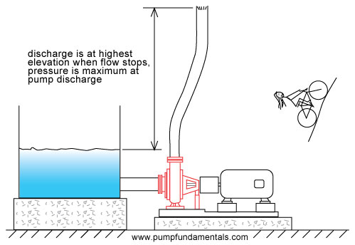
Figure 12
If the discharge pipe end is lower than the liquid surface of the suction tank then the static head will be negative and the flow rate high (see Figure 13). If the negative static head is large then it is possible that a pump is not required since the energy provided by this difference in elevation may be sufficient to move the fluid through the system without the use of a pump as in the case of a siphon (see pump system glossary). By analogy, as the cyclist comes down the hill he looses his stored elevation energy which is transformed progressively into velocity energy. The lower he is on the slope, the faster he goes.

Figure 13
Pumps are most often rated in terms of head and flow. In Figure 12, the discharge pipe end is raised to a height at which the flow stops, this is the head of the pump at zero flow. We measure this difference in height in feet (see Figure 13a). Head varies depending on flow rate, but in this case since there is no flow and hence no friction, the head of the pump is THE MAXIMUM HEIGHT THAT THE FLUID CAN BE LIFTED TO WITH RESPECT TO THE SURFACE OF THE SUCTION TANK. Since there is no flow the head (also called total head) that the pump produces is equal to the static head.

Figure 13a
In this situation the pump will deliver its maximum pressure. If the pipe end is lowered as in Figure 10, the pump flow will increase and the head (also known as total head) will decrease to a value that corresponds to the flow. Why? Let's start from the point of zero flow with the pipe end at its maximum elevation, the pipe end is lowered so that flow begins. If there is flow there must be friction, the friction energy is subtracted (because it is lost) from the maximum total head and the total head is reduced. At the same time the static head is reduced which further reduces the total head.

When you buy a pump you don’t specify the maximum total head that the pump can deliver since this occurs at zero flow. You instead specify the total head that occurs at your required flow rate. This head will depend on the maximum height you need to reach with respect to the suction tank fluid surface and the friction loss in your system.
For example, if your pump is supplying a bathtub on the 2nd floor, you will need enough head to reach that level, that will be your static head, plus an additional amount to overcome the friction loss through the pipes and fittings. Assuming that you want to fill the bath as quickly as possible, then the taps on the bath will be fully open and will offer very little resistance or friction loss. If you want to supply a shower head for this bathtub then you will need a pump with more head for the same flow rate because the shower head is higher and offers more resistance than the bathtub taps.
Luckily, there are many sizes and models of centrifugal pumps and you cannot expect to purchase a pump that matches exactly the head you require at the desired flow. You will probably have to purchase a pump that provides slightly more head and flow than you require and you will adjust the flow with the use of appropriate valves.
Note: you can get more head from a pump by increasing it’s speed or it’s impeller diameter or both. In practice, home owners cannot make these changes and to obtain a higher total head, a new pump must be purchased.
For identical systems, the flow rate will vary with the size and diameter of the discharge pipe. A system with a discharge pipe that is generously sized will have a high flow rate. This is what happens when you put a large pipe on a tank to be emptied, it drains very fast.
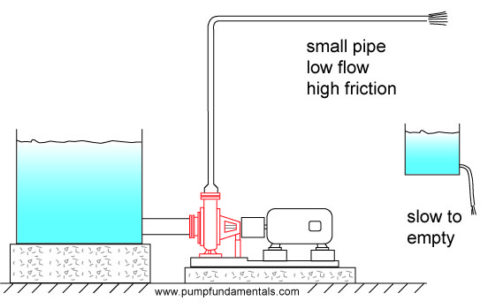
Figure 14
The smaller the pipe, the less the flow. How does the pump adjust itself to the diameter of the pipe, after all it does not know what size pipe will be installed? The pump you install is designed to produce a certain average flow for systems that have their pipes sized accordingly. The impeller size and its speed predispose the pump to supply the liquid at a certain flow rate. If you attempt to push that same flow through a small pipe the discharge pressure will increase and the flow will decrease. Similarly if you try to empty a tank with a small tube, it will take a long time to drain (see Figure 15).
Later on in the tutorial, a chart will be presented giving the size of pipes for various flow rates. Or you can jump to it right away and come back later.

Figure 15
If the pipe is short the friction will be low and the flow rate high (see Figure 16).
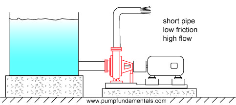
Figure 16
and when the discharge pipe is long, the friction will be high and the flow rate low (see Figure 17).

Figure 17
How does a centrifugal pump produce pressure
Fluid particles enter the pump at the suction flange or connection. They then turn 90 degrees into the impeller and fill up the volume between each impeller vane.
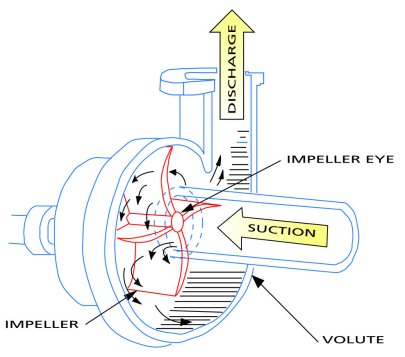
Figure 19
A more detail look at a more realistic cross-section of a closed impeller pump can be seen in Figure 19a
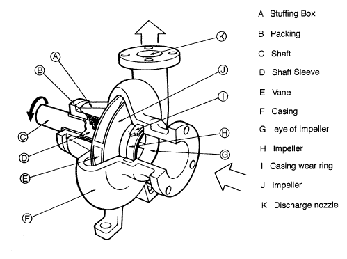
Figure 19a
A centrifugal pump is a device whose primary purpose is to produce pressure by accelerating
fluid particles to a high velocity providing them with velocity energy. What is velocity energy?
It's a way to express how the velocity of objects can affect other objects, you for example.
Have you ever been tackled in a football match? The velocity at which the other player comes at
you determines how hard you are hit. The mass of the player is also an important factor. The
combination of mass and velocity produces velocity (kinetic) energy. Another example is catching a hard
baseball pitch, ouch, there can be allot of velocity in a small fast moving baseball. Fluid
particles that move at high speed have velocity energy, just put your hand on the open end
of a garden hose.
The fluid particles in the pump are expelled from the tips of the impeller vanes at high velocity, then they slow down as they get closer to the discharge connection, loosing some of their velocity energy. This decrease in velocity energy increases pressure energy. Unlike friction which wastes energy, the decrease in velocity energy serves to increase pressure energy, this is the principal of energy conservation in action. The same thing happens to a cyclist that starts at the top of a hill, his speed gradually increases as he looses elevation. The cyclist’s elevation energy was transformed into velocity energy, in the pump’s case the velocity energy is transformed into pressure energy.
Try this experiment, find a plastic cup or other container that you can poke a small pinhole in the bottom. Fill it with water and attach a string to it, and now you guessed it, start spinning it.

Figure 20
The faster you spin, the more water comes out the small hole, the water is pressurized inside the cup using centrifugal force in a similar fashion to a centrifugal pump. In the case of a pump, the rotational motion of the impeller projects fluid particles at high speed into the volume between the casing wall and the impeller tips. Prior to leaving the pump, the fluid particles slow down to the velocity at the inlet of the discharge pipe (see Figures 18 and 19) which will be the same velocity throughout the system if the pipe diameter does not change.
How does the flow rate change when the discharge pipe end elevation is changed or when there is an increase or decrease in pipe friction? These changes cause the pressure at the pump outlet to increase when the flow decreases, sounds backwards doesn’t it. Well it’s not and you will see why. How does the pump adjust to this change in pressure? Or in other words, if the pressure changes due to outside factors, how does the pump respond to this change.
Pressure is produced by the rotational speed of the impeller vanes. The speed is constant. The pump will produce a certain discharge pressure corresponding to the particular conditions of the system (for example, fluid viscosity, pipe size, elevation difference, etc.). If changing something in the system causes the flow to decrease (for example closing a discharge valve), there will be an increase in pressure at the pump discharge because there is no corresponding reduction in the impeller speed. The pump produces excess velocity energy because it operates at constant speed, the excess velocity energy is transformed into pressure energy and the pressure goes up.
All centrifugal pumps have a performance or characteristic curve that looks similar to the one shown in Figure 21 (assuming that the level in the suction tank remains constant), this shows how the discharge pressure varies with the flow rate through the pump.
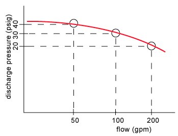
Figure 21
So that at 200 gpm, this pump produces 20 psig discharge pressure, and as the flow drops the pressure will reach a maximum of 40 psig.
Note: his applies to centrifugal pumps, many home owners have positive displacement pumps, often piston pumps. Those pumps produce constant flow no matter what changes are made to the system.
see the effect of static head on flow rate in action in this video![]()
Copyright 2019, PumpFundamentals.com