|
Web www.lightmypump.compumpfundamentals.com |
|
Web www.lightmypump.compumpfundamentals.com |
MICRO-HYDRO INSTALLATION SIZING CALCULATIONS
Download a pdf version![]() of this web page.
of this web page.
Calculations for micro-hydro turbine jet impact velocity are based on the same sort of calculations done for pump systems, except there is no pump. The energy is provided by the difference in elevation between the inlet and outlet of the system (see Figure 1). The inlet (point 1) is defined as the surface elevation of the water source and the outlet is at the nozzle outlet (point 2).
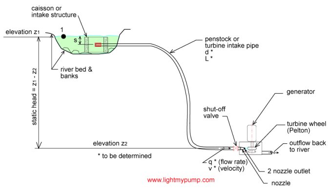
Figure 1
The general equation for fluid flow between two points is:
where z1 and z2 are respectively the elevation at points 1 and 2. We also have velocity and pressure head at points 1 and 2.
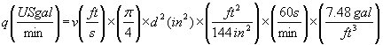
Calculating velocity from flow rate
The flow rate in a pipe depends on velocity and surface area:
since the surface area for a pipe is pd2/4. Using consistent units in the Imperial system we obtain:
`
and after simplification:
or
Imperial units
Metric units
Calculating nozzle velocity v2
The velocity v1 is the velocity of fluid particles at the water source surface (see Figure 1), this velocity will be quite small and negligible, v1 =0. The velocity v2 is the velocity of the water jet at the nozzle; this is the quantity we are looking for. The pressure head H1 corresponds to any external pressure that might be imposed at point 1, in this case it is zero, H1 = 0. The pressure head H2 is the pressure at the outlet of the nozzle, since the water jet comes out in the free atmosphere H2 = 0. HF is the friction loss between points 1 and 2, it is comprised of the pipe friction loss, filter intake loss, fittings and manual valve losses. g is the acceleration due to gravity, g = 32.17 ft/s2. If we replace these values into equation (1) we obtain:
v2 becomes:
Imperial units
Metric units
Solving equation (5) is an iterative process, first we give a trial value to the flow rate q and then calculate and from this result we then calculate v2 again based on equation (5). If the values are different we modify the value of v2 and try again until are trial value is the same as the calculated value.
Or you can use the formulas that are explained on this page to do direct calculations:
https://www.pumpfundamentals.com/help14.html
Calculating available power
The design of the Pelton turbine is such that it is at it's most efficient when its peripheral speed is half the speed of the incoming water jet. See this web page for a good explanation of how power is derived for a Pelton turbine:
The power in the water jet is equal to γhq where γ gamma is the specific weight of water, h is the available head and q the flow rate. If we know the velocity, the power can be expressed as 1/2ρv2q where ρ rho is the water density and v the water jet nozzle velocity. Either one of these expressions gives the theoretical power available from the water jet.
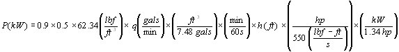
The Pelton turbine is designed to produce maximum power when the peripheral speed is 1/2 of the water jet speed. The power transmitted to the turbine wheel is 0.5γhq. The 50% is theoretical and is based on the fact that the water jet is reversed due to the wheel cup design 180 degrees back towards its source. The reversed water jet is not exactly in line so that the wheel itself has a real world efficiency of 90% or better. Therefore that power at the turbine wheel is:
0.9 x 0.5 x γ x h x q
using Imperial units:
or in metric units:
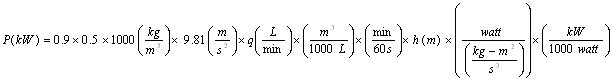
which simplifies to:
Imperial units
Metric units
If we use the formula using nozzle velocity:
where ρ is the density and q the volumetric flow rate. To make all the units consistent in the Imperial system the power P in equation (7) must be divided by the constant gc, using the proper units with their conversion factors and the water density of 62.34 lbm/ft3, we obtain:

which simplifies to:
or in metric units
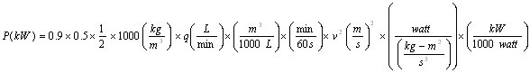
which simplifies to:
Calculating turbine speed
The turbine peripheral velocity will be half the water jet velocity.
The equation for rotational vs. peripheral velocity is:
where ω omega is the rotational velocity in radians/second and d the diameter of the turbine wheel. We would like to use the units of rpm for ω and inch for d. Therefore equation (10) becomes:
Imperial units
 (11-1)
 Metric units
and after simplification equation (11) becomes:
or in metric units
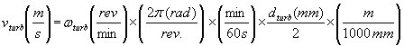
by replacing the value of vturb in equation (9) into equation (11) we obtain:
or in metric units
therefore the rotational velocity of the turbine is:
or in metric units