The siphon
or understanding how pressure varies in a pump system
Jacques Chaurette
April 2016
download in pdf format
A siphon is a way of draining a tank at a high level from the top to another one at a lower level. The tank is not drained from the
bottom but by a tube that exits the upper tank from the top and then turns downward to the lower tank. Or it could be from the side as
long as one part of the tube goes above the liquid surface of the top tank. Surprisingly the liquid will move upward against gravity,
a feat not possible in the world of solids.
This is due to low pressure that keeps the liquid in the top part of the siphon from falling and the connection between fluid particles that pressure provides.
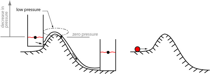 Figure 1 Siphoning a liquid vs. moving a solid.
Pressure in liquid systems is due to the weight of liquid above a surface. If we know the height and the density of the liquid we can calculate the pressure.
Pressure is the same on any given horizontal plane and at any given point depends only on its vertical position with respect to some reference point.
Pressure can also vary due to friction when the liquid is moving but in this case we can assume that the friction is very low since the liquid is
moving slowly.
Since the liquid is moving upwards it seems as if we are getting free energy, but we are not. While making the siphon we store positional or
potential energy by lifting the fluid up in the top part of the siphon before it is set in motion. That's like putting the solid ball on top of the hump.
 Figure 2 Providing energy to the solid.
One way the fill a siphon is to apply suction at the top as if using a straw.
 Figure 3 Filling a siphon
The low pressure applied using suction is necessary to suspend the liquid in the tube.
If we take a small section of the tube we see that the only way for the liquid to be suspended is for low pressure and the force it produces F
1 to
be present on the top side of a slice while the higher pressure at the bottom produces a higher pressure and its corresponding force F
0. These
forces balance out the weight of the liquid W.
 Figure 4 Balancing the weight of the liquid using low pressure.
The pressure at the bottom of a reservoir depends on the amount of liquid (weight). If we divide the weight by the area we get pressure. If we know the
density ρ g and the height of liquid h, the pressure is ρ g h. The pressure at any point in the liquid is positive or above atmospheric. We can
generate low pressure by making a siphon.
 Figure 5 Pressure vs. height in a body of liquid.
The making of a siphon
Figure 5 Pressure vs. height in a body of liquid.
The making of a siphon
Let's build a siphon from scratch to see how it really works.
Case A (see Figure 6 and 7)
A horizontal tube is filled with water between 2 reservoirs (see Figure 7). The pressure in the tube will be proportional to the height in the reservoirs,
that's because as we move upwards pressure in the liquid column decreases since there is less water to provide weight and therefore pressure. This is similar
to what happens in a swimming pool (see Figure 5) as you move from the bottom of the deep end to the surface, pressure decreases and reaches zero or
atmospheric pressure at the surface.
As the tube is stretched upwards the pressure in the tube at the high point decreases, when the high point of the tube reaches the surface level in the
reservoir the pressure is zero or atmospheric.
In our case since we have liquid in a tube it is possible to decrease the pressure below atmospheric. In the absolute scale atmospheric pressure is 14.7
psia at sea level and the exact value of pressure in the tube for a given elevation will depend upon the height above the liquid surface.
 Figure 6 Preparing a siphon.
Case B
As we stretch the tube higher (see Figure 6), pressure drops further below atmospheric and decreases by an amount proportional to the difference
in height between the top of the tube and the reservoir level. This is the beginning of a siphon whose main characteristic is low pressure at the high
point. Low pressure prevents the liquid from falling to the liquid level of the reservoirs.
Case C
As we move one reservoir up the slope (see Figure 7) the portion of low pressure within the tube gets smaller. The intersection of a line drawn
horizontally between the level of the reservoir and the tube indicates the point of zero pressure within the tube. The liquid below this intersection
wants to drop in free fall to the reservoir below. As it drops it entrains the liquid above it which is connected to the top reservoir.
Why does the liquid move up in the siphon?
The weight of that portion of liquid at the top is balanced by low pressure like 2 weights over a pulley. It takes no effort to move one weight up
vertically, similarly that portion of liquid can move without any effort. As the liquid drops on the right side it
entrains the liquid in the low
pressure area which is replaced by the liquid in the upper reservoir.
 Figure 7 The liquid in a siphon in balance similarly to two weights over a pulley.
Case D
The last case shows the top reservoir at its maximum height. All the liquid in the tube wants to drop into the bottom reservoir. This is not a
siphon but simply one tank draining into another by gravity.
 Figure 8 Making a siphon step by step.
Are there any practical uses for a siphon?
Figure 8 Making a siphon step by step.
Are there any practical uses for a siphon? You could drain or fill the tank of your car or you could drain your plugged sink. What about
industry, do they use siphons? It's not very common, there is usually no compelling need. However knowing how a siphon works can avoid embarrassing
mistakes which I will elaborate on later.
The reverse siphon
A reverse siphon is a pump system providing upward flow entering the receiving tank from above. This is quite common in industry. The siphon is similar, the flow is downward and
there is no pump. The main difference between the two systems is the direction of the liquid, seeing as the liquid can't tell which direction
it's going there will also be low pressure at the high point in the pump system.
 Figure 9 Pressure levels within a siphon compared to a pump system.
As we can see the pressure profile is very similar in the siphon or pump system as expected. In comparing the two pressure profiles we see that
the main difference is the pressure level between points 7 and 8, this is where energy is injected by the pump to move the liquid against gravity.
Avoiding a bad connection
People who have only a casual acquaintance with pump systems are unaware that pressure varies drastically throughout the system. And frankly you
normally don't need to consider this if you are just sizing a pump for a particular application. All you need to know is the flow rate required,
the difference in elevation between the two liquid surfaces of the tanks and the friction due to velocity in the pipe. Because of that there
is a mistaken belief that the pressure is mostly constant throughout the system.
What if you were to put a connection at the top of the pipe to feed some other equipment? You would have to speed up the pump or increase
the impeller size to get the extra flow required to that connection.
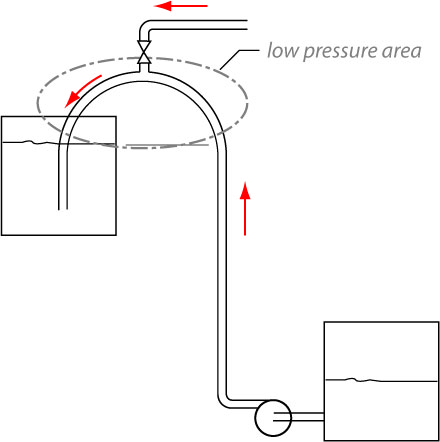 Figure 10. Trying to make a connection in a low pressure area.
Make your own siphon
Figure 10. Trying to make a connection in a low pressure area.
Make your own siphon

This is two glasses with some plastic tubing and a wire to hold the tube up.
Demonstration model
Here's a demonstration model I intend to build.

There are a few devices not shown, springs to store the energy when one reservoir is completely at the bottom thereby balancing the
weight of the heavier reservoir and a pusher on each side to start the cycle again.
Ref: A very comprehensive description of siphons:
Wikipedia siphon
Copyright 2019, PumpFundamentals.com