Help for calculating maximum allowable piping pressure according to the ASME pressure piping code B31.3
Applets are programs based on the java language that are designed to run on your computer using the Java Run Time environment.
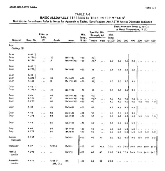
The ASME code recommends an allowable tensile stress level in the pipe material (see the terminology section at the end of this article). The pressure that can generate this tensile stress level can be calculated taking into account the type of material, temperature and other factors.
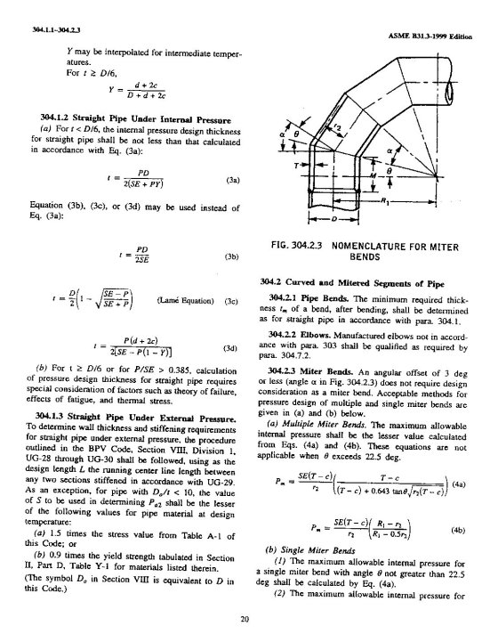
The formula (see B31.3-1999 code, page 20) which gives the relationship between the pressure (p) labeled p (see equation[1]), the outside diameter (D), the allowable tensile stress (S) and the thickness (t) of the pipe is:
 [1]
[1]
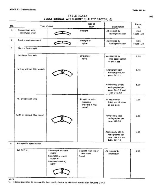
where E: material and pipe construction quality factor as defined in ASME Process Piping code B31.3-1999, Table A-1A
Y: wall thickness coefficient with values listed in ASME Process Piping code B31.3-1999, Table 304.1.1
Formula [1] is re-written in terms of the pressure (p) of the fluid within the pipe:

Calculation example
The pipe is a typical spiral-weld construction assembled according to the specification ASTM A 139-96. The material is carbon steel ASTM A 139. The outside diameter of the pipe is 20.5 inches and the wall thickness is 0.25-inch.
For this material, the ASME code recommends that an allowable stress (S) of 16,000 psi be used for a temperature range of -20°F to +100°F. The quality factor E for steel A139 is 0.8; the wall thickness coefficient Y is 0.4.
| Material | Minimum tensile strength(psi) | ASME code Allowable stress (S)(psi) |
| ASTM A139 | 48000 | 16000 |
The value of the internal fluid pressure that will produce the tensile stress level stipulated by the ASME code is 315 psig (see formula [3]).

This pressure should be compared to the normal operating pressure. The pressure in a pump system can vary dramatically from place to place. The pressure level vs. location can only be determined on a case by case basis. However, typically the pressure is maximum near the pump discharge and decreases towards the outlet of the system.
It is possible that the system could be plugged. When the system plugs, the pump head increases and reaches (at zero flow) the shut-off head in the case of a centrifugal pump. The maximum pressure in the pump system will then be the pressure corresponding to the shut-off head plus the pressure corresponding to the pump inlet suction head. Since the system is plugged, this pressure will extend all the way from the pump discharge to the plug if the plug is at the same elevation as the pump discharge. The relationship between pressure head and pressure is given in equation [4].
![]()
where (H) is the pressure head, (p) the pressure and (SG) the specific gravity of the fluid.
If the shut-off pressure exceeds the allowable operating pressure as calculated by the ASME code, then pressure relief devices may have to be installed. This is not likely to occur in single pump systems, but multiple series pump systems may produce excessive shut-off pressures since the pressure at the outlet of the last pump depends on the sum of the shut-off pressures of each pump. Exceptions are provided for in the code and are relative to the duration of the maximum pressures events, if they are of short duration these events may be allowed for short periods.
Rupture disks are often used in these situations. They are accurate, reliable pressure relief devices. However, these devices are not mandatory in many systems and their installation are then a matter of engineering judgment.
Existing systems
In an existing system, one should not rely on the original thickness of the pipe to do the pressure calculations. The pipe may suffer from corrosion, erosion or other chemical attacks which may reduce the wall thickness in certain areas. The pipe wall thickness can easily be measured by devices such as the Doppler ultra sound portable flow meter. The smallest wall thickness should be used as the basis for the allowable pressure calculations or the damaged areas should be replaced.
New systems
In new systems, consider if a corrosion allowance (depending on the material) should be used. The corrosion allowance will reduce the wall thickness that is used in the allowable pressure calculations.
Also the piping code allows pipe manufacturers a fabrication tolerance which can be as high as 12.5% on the wall thickness, this allowance should be considered when determining the design pipe wall thickness.
Terminology
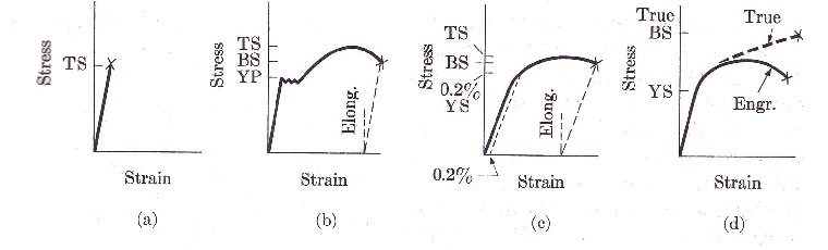
Figure 1 shows the location of the various stress levels in a typical stress vs. strain graph.
TS: Tensile strength
YP: Yield point
BS: Breaking strength
The following four figures are excerpts from the ASME Power Piping Code B31.3

This pdf document![]() provides information on different flange pressure ratings, construction, ANSI class and materials base on the ASME code B16.5.
provides information on different flange pressure ratings, construction, ANSI class and materials base on the ASME code B16.5.
This applet will help you calculate the allowable pressure according to the pressure piping code B31.3. You can download![]() an example of this type of calculation as well as the formulas used including an extract of the pressure piping code. The formula for max. pressure is based on the well known hoop stress formula in which two additional factors have been added, Y a factor based on the type of steel and E a factor based on the type and quality of the weld. The pressure piping code is not readily available on the internet. You can probably find it in your local technical university or college librairy. The book "Piping Handbook" by Mohinder L. Nayyar published by McGraw Hill has extracts of the code. Remember that when you check the maximum allowable piping pressure you must also check the maximum allowable flange pressure, this depends on the ANSI class of the flange, the material and the temperature.
an example of this type of calculation as well as the formulas used including an extract of the pressure piping code. The formula for max. pressure is based on the well known hoop stress formula in which two additional factors have been added, Y a factor based on the type of steel and E a factor based on the type and quality of the weld. The pressure piping code is not readily available on the internet. You can probably find it in your local technical university or college librairy. The book "Piping Handbook" by Mohinder L. Nayyar published by McGraw Hill has extracts of the code. Remember that when you check the maximum allowable piping pressure you must also check the maximum allowable flange pressure, this depends on the ANSI class of the flange, the material and the temperature.